![]()
![]()
![]()
![]()
 |
|
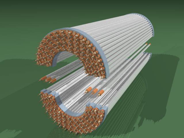
| Tube's diameter | 10мм. |
| Length of sensitive area | 670мм. |
| Anode wire | W, 20мкм. |
| First layer radius | 67.1мм. |
| Last layer radius | 116.84мм. |
| Number of the layers | 6 |
| Full number of the tubes | 312 |
sigmad=2.2*sigma0,
where sigma0 is the r-fi resolution in a single tube. The contribution of multiple scattering is 40 mcm/P [GeV] and results mainly from the material of the vacuum chamber and the inner wall of the vertex chamber. The longitudinal coordinate is not measured by the vertex chamber.
Last modified on 26 September 2000